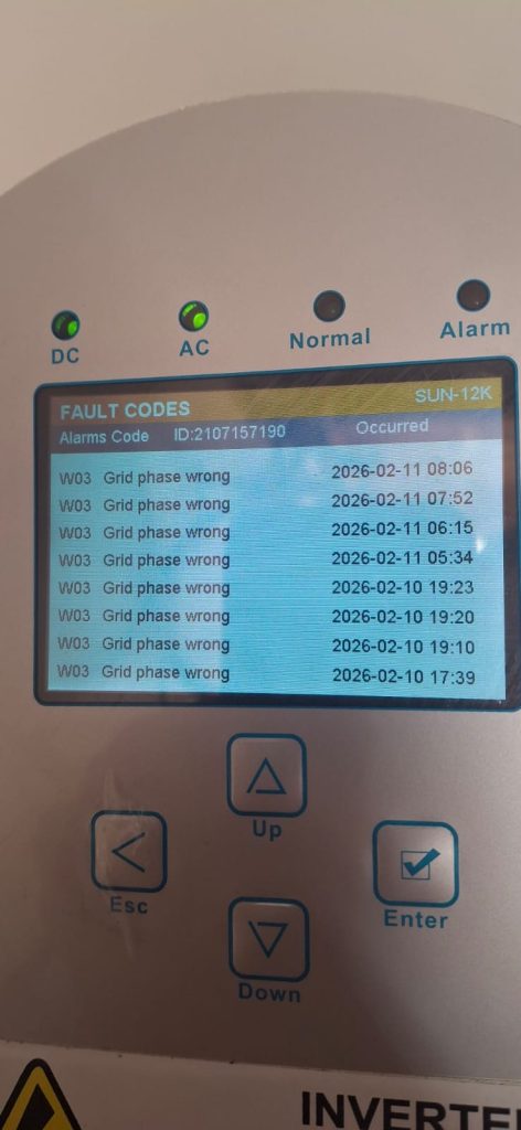
This was a site I was called out to where a 12kW 3 Phase Sunsynk inverter kept periodically presenting a W03 (or grid phase wrong fault). It would go in to W03 randomly and then clear the error itself after a while.
Now normally a W03 is just a phase rotation error and can be rectified by swapping any 2 phases on the grid side to the inverter, you can also, if you have remote access to settings, change the rotation this way (changing from 0,120,240 to 240,120,0), however I would always suggest issues like this be resolved on site rather than remotely. In this case however, the problem is NOT a phase rotation issue as the error is periodic and not constant (a true phase rotation error would be constant, not periodic).
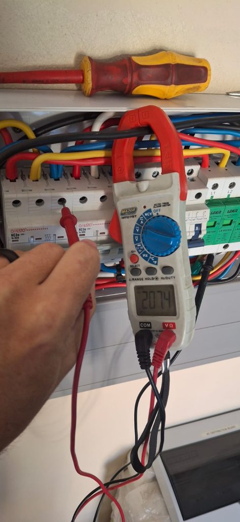
So have a look at this and see what went wrong and how we go about rectifying this. A good tool to have of course would always be a phase rotation tester when working with 3 phase equipment, but it was evident in this case that one would not be needed on this site. I started with a simple check, just looking at the inverters on screen data to see what could be deduced from there.
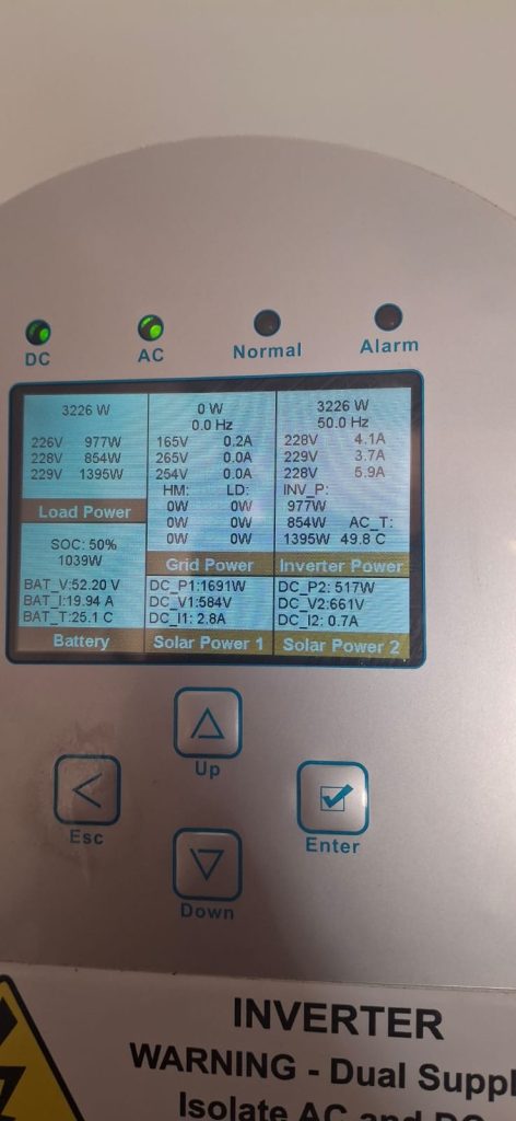
We can immediately see from the inverters data that the grid phase voltages are far out of range for it to properly accept the grid from it. Phase 1 is getting dropped due to it falling below its accepted 180v from grid. So suddenly the inverter is only receiving 2 phases. The inverter does not interpret this as a grid loss, it sees it as a phase rotation fault, thus presenting the W03 warning.
The intermittency of the W03 warning is being caused by a voltage drop on L1 and then clears itself once that voltage comes back in range of what the inverter is allowed to accept. So, it now becomes a case of determining why the voltage on L1 is so unstable.
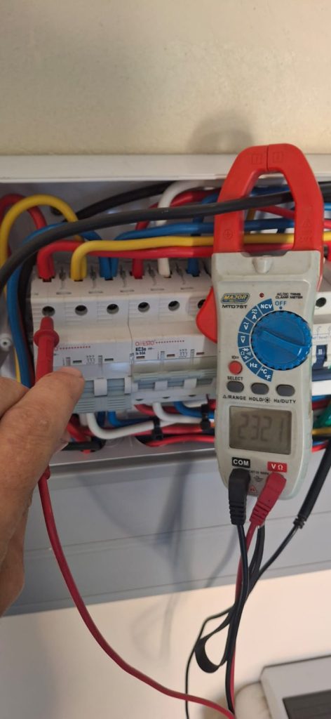
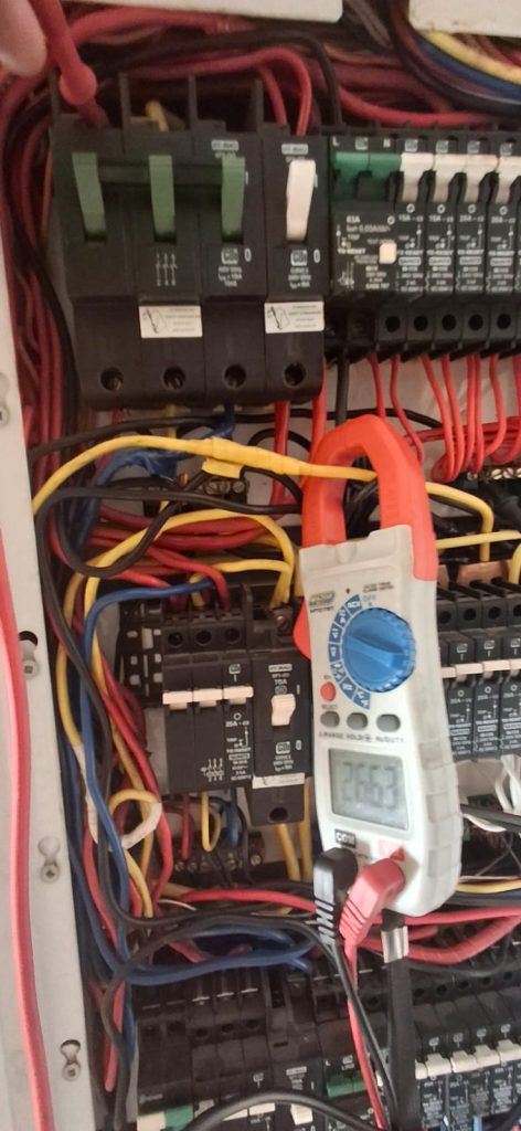
For this part of the process, I prefer to start from as close as possible to where the problem is being presented then slowly work back from there. So i started in the inverters isolation DB, the closest point of switching to the inverter. As we can see in the images above, L2 and L3 are about where we wan them to be, L1 however, matches more to what we’re seeing on the inverters data. So the fault exists further back.
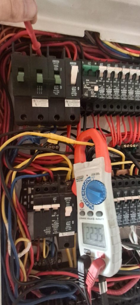
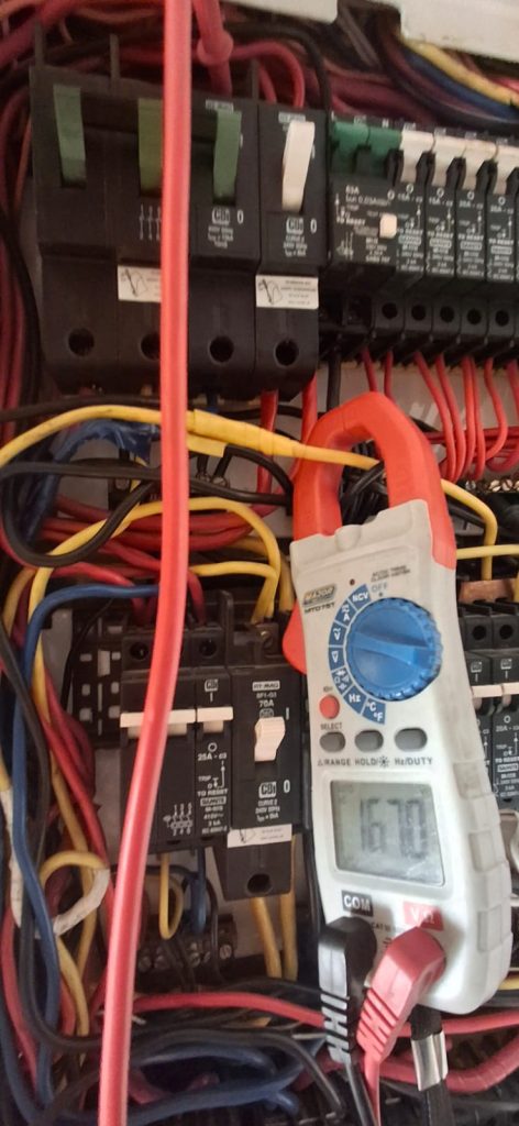
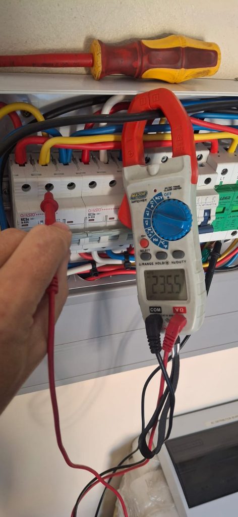
Our next step was a trip to the main supply DB which is point of switching for the inverters supply DB. Voltages were measured as close as possible to where its supply came in (which is the line side of the main breaker), this is the point where any further back is council point of switching. Our voltages here measured similar to at the inverters DB and what the inverters data was giving us.
I wasn’t able to go any further back to measure on council side as that point was inaccessible to me.
This does however conclude that the problem with this is a bad connection on council side and will have to be rectified by them. Until then, the inverter is still protecting the loads after it, if anyone of the 3 phases voltage to neutral go out of range, the inverter immediately switches to off grid mode and presenting the misunderstood W03 fault and reintroduces grid back to it once voltages come back within range.