This one took time.
Not because the fix was complicated, but because nothing made sense at first.
To make it worse, the site wasn’t accessible to me physically. We have installations across the country and this one was too far out, so everything had to be done remotely. All I had to work with was:
- Logger data
- Trend graphs
- Photos from site
- A local technician I could direct
On top of that, the site had municipal supply issues at the same time. One of the three phases had a burned main breaker that had been temporarily replaced with an undersized single-pole breaker. That breaker kept tripping, so we were also seeing grid phase faults mixed into everything.
So initially, it was noisy, electrically and diagnostically.
System Setup
- Three-phase inverter
- Two battery banks
- Originally configured in parallel (single battery channel enabled)
- Only one BMS communication cable connected
The reported issue was a repeating F58 BMS Communication Fault.
The fault would:
- Trigger roughly every 10 minutes
- Clear after about 2 minutes
- Repeat continuously
The inverter would recover on its own, then F58 fault again shortly after.
First Thought – Incorrect BMS Configuration
Because there were two battery banks running in parallel but only one BMS cable connected, my first assumption was that communication topology was wrong.
So we changed it:
- Disabled parallel battery setting
- Switched to dual channel mode
- Ran separate BMS cables:
- Bank 1 to BMS1
- Bank 2 to BMS2
Logically, this should have cleaned things up.
It made absolutely no difference.
At that point I knew it wasn’t just a configuration issue.
Second Direction – Grid Instability
Because of the municipal breaker issue, I shifted focus to the AC side.
The system was bypassed temporarily, which gave me room to experiment without risking shutdowns to the site.
I started playing with operational states.
Here’s where it got interesting.
If I disabled export to grid-tied loads, the fault stopped completely.
As soon as export resumed, the F58 fault came back.
That was the first real clue.
Controlled Testing
I then started deliberately manipulating current.
High discharge
Let the batteries discharge at maximum current.
Fault returned almost immediately.
Let battery rest
Once battery reached its discharge floor and current dropped.
Fault stopped.
Forced charge at 5A
Charged cleanly. No fault.
Increased to 50A
Fault immediately returned.
Reduced to 10A
Stable again.
That pattern was too consistent to ignore.
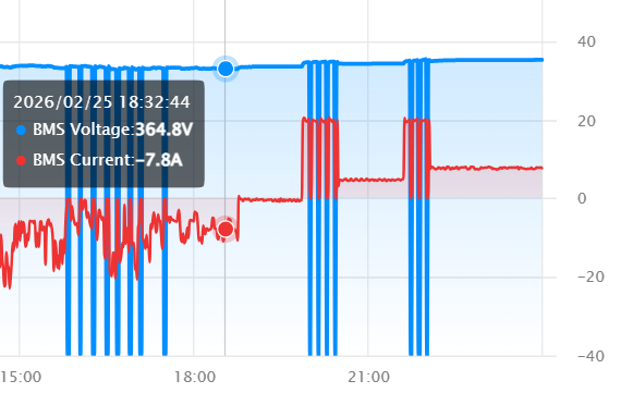
You can see by the image below, the moment charge currents were increased from small amounts to larger amounts, the BMS communication loss occurs as listed above.
Pattern Identified
The F58 fault only occurred when there was high AC current at the inverter.
Specifically:
- High charge current (large AC input current)
- High discharge current (large AC output current)
- High export during PV production
When current was low — the system was stable.
That ruled out:
- Random firmware instability
- Pure battery failure
- Inverter hardware defect
- Grid frequency behaviour
The variable was current magnitude.
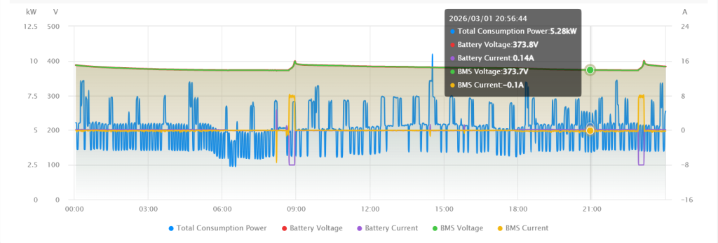
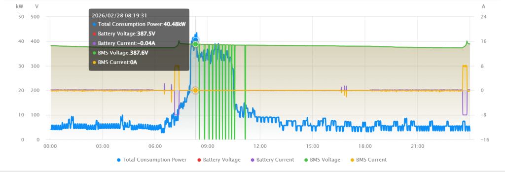
Further evidence to this can be seen in the below images where if a high AC current is present at the inverter, we can see the same BMS communication loss. When grid currents are low, there is no BMS communication loss (batteries are not charging nor discharging at this point, inverter is set to keep batteries charged).
What That Left
At that point, there was only one logical direction left:
Interference.
The BMS cable was running near high-current AC conductors.
Under heavy load, electromagnetic noise was being induced onto the communication line.
That explained the behaviour perfectly:
- Inverter starts charging
- High current flows
- Interference corrupts BMS signal
- Inverter logs comm fault
- Charging stops
- Current drops
- Interference disappears
- Inverter recovers
- Charging resumes
- Cycle repeats
The 10-minute repetition lined up with retry behaviour.
Both the battery manufacturer and inverter manufacturer had initially pointed fingers at each other. In reality, both devices were doing exactly what they should.
The problem wasn’t either device.
It was the communication layer between them.
Fix
We:
- Replaced the BMS cable with shielded CAT6
- Rerouted it away from AC and DC power cables
- Added a ferrite toroid to suppress high-frequency noise
- Ensured no parallel runs alongside high-current conductors
After that:
- No recurrence of the F58 BMS comm fault
- Stable high-current charging
- Stable discharge
- No cyclical shutdowns
System has been operating normally since.
Takeaways
- If a communication fault appears cyclical and load-dependent, suspect interference.
- High-current environments demand proper cable routing.
- Shielding and physical separation matter more than most people think.
- Always isolate the variable before replacing hardware.
- If two manufacturers are blaming each other, go back to fundamentals.